This retrofit guide for BMW M5 Saloon (F10M) and BMW M6 Grand Coupé/Convertible/Coupé (F06M/F12M/F13M)
Retrofit kit number 32 30 2 344 136 M Performance steering wheel with Race Display
Installation information
- Ensure that the cables and/or lines are not kinked or damaged as you install them in the car.
- Additional cables/lines that you install must be secured with cable ties.
- If the specified PIN chambers are occupied, bridges, double crimps or twin-lead terminals must be used.
- All pictures show LHD cars. Once the installation work is complete, basic settings need to be carried out on the M Performance steering wheel.
- If fitted with SA 248 (heated steering wheel), the heating function will not work, the heating key on the steering column will have no function when fitted. An error memory entry be made in the control unit but this can be ignored.
- M5 cars built before 07/13 – Airbag unit, multi-function keys and possibly shift paddles as well as steering wheel electronics (cable, control unit and vibration generators) must be ordered for a new M Sport steering wheel (from 07/13) and replaced.
- M5 cars built after 07/13 and – all M6 cars – Adoption of all parts possible.
For cars without at least one of the following SAs
On cars without at least one of the following SAs, a new steering column switching centre (SCSC) must be installed in order to carry the signals to the steering wheel electronics:
- SA 248 Heated steering wheel
- SA 5AD Lane departure warning
- SA 5AG Lane change warning
- SA 5AR Traffic jam assistant
- SA 5AS Driving Assistant
- SA 5AT Driving Assistant Plus
In this case, a corresponding 4-band SCSC must be retrofitted, depending on whether the car is equipped with the High Beam Assistant (SA 5AC) or not. The part numbers for the 4-band SCSC are as follows:
- For cars without SA 5AC – Part No. 61 31 9 354 047
- For cars with SA 5AC – Part No. 61 31 9 354 048
1. Parts list for the M Performance steering wheel with Race Display
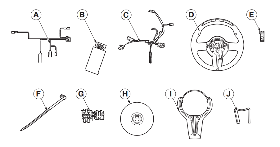
- A Retrofit cable
- B Control unit
- C Steering wheel adapter cable (already fitted to M Performance steering wheel)
- D M Performance steering wheel
- E SW 2-pin socket casing
- F Cable ties (15 x)
- G Miniature connector (2 x)
- H Airbag module (not supplied with the retrofit kit)
- I Trim for M Performance steering wheel
- J Clamp spring
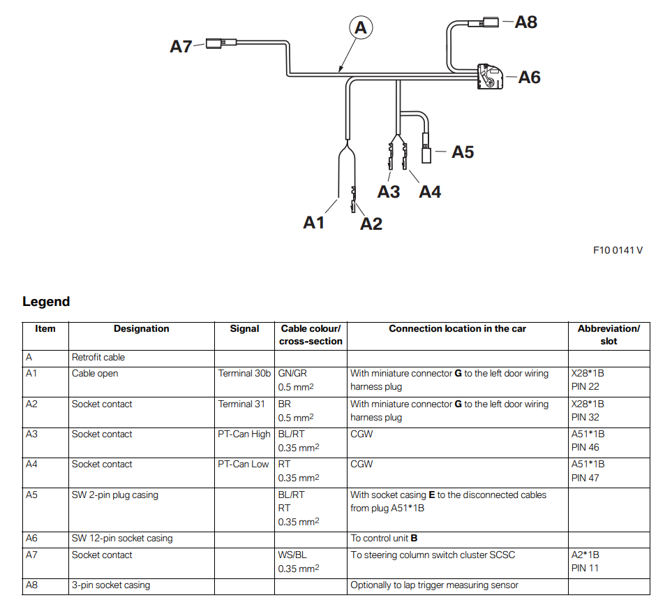
2. Connection diagram for the M Performance steering wheel with Race Display
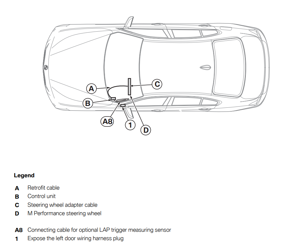
3. Installation and cabling diagram for the M Performance steering wheel with Race Display
4. Removal of the steering wheel

- On cars with manual transmission (SA 2MA), no shift paddles are present.
- Only if lane change warning (SA 5AG) or lane departure warning (SA 5AD) or DRIVING ASSISTANT (SA 5AS) are installed: Disconnect the plug (4) from the vibration generator (5).
- Only if steering wheel heating (SA 248) is installed: remove the plug (6) from the control module (7).
- The control module (7) will only be present if a lane departure or lane change warning or DRIVING ASSISTANT and/or a steering wheel heating system are fitted. This control module (7) must be included in the new steering wheel.
- For all cars: The wiring harness (8) remains in the standard steering wheel and is not required.
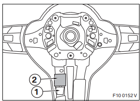

Only if lane change warning (SA 5AG) or lane departure warning (SA 5AD) or DRIVING ASSISTANT (SA 5AS) are installed:
If there is a piece of foam on the vibration generator (1), this must be removed and replaced during installation. When the clamp spring (2) is being removed, push firmly upwards on the clamp spring (2) to release the barb at the bottom of the clamp spring (2).
- Remove the clamp spring (2) from the vibration generator (1) and remove the vibration generator (1).
- If the clamp spring (2) is damaged during removal, it should not continue being used and must be replaced by new clamp spring J.

For all cars:
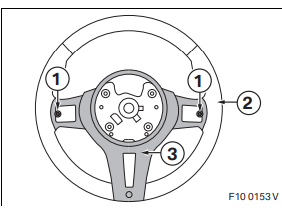
- Loosen and remove the screws (1) on the back of the steering wheel (2).
- Remove the rear cover (3).
- Remove the steering wheel (2).
4. Installation of the M Performance steering wheel with Race Display retrofit kit

Only for M5 cars:
- To make access to the Central Gateway (CGW) in the left footwell easier, the cover (1) can be removed if fitted.

For all cars:
- Remove plug A51*1B from the CGW (1) in the left footwell.

- Connect branch A1, GN/GR cable, with RT/GR cable from PIN 22 to left door wiring harness X28*1B using miniature connector G.
- Remove socket contact A2 using suitable tools.
- Connect branch A2, BR cable, with BR cable from PIN 32 to left door wiring harness X28*1B using miniature connector G.

- Disconnect PIN 46 and PIN 47 from A51*1B and connect to plug E so that plug A5 can be connected using the same colours to plug E.
- Connect branch A3, BL/RT cable, to A51*1B PIN 46.
- Connect branch A4, RT cable, to A51*1B PIN 47. Then connect plug A51*1B to the CGW and plug A16*1B to the CAS.

- Secure control unit B to a suitable point on the wiring harness using cable tie F.
- Tie back LAP trigger cable A8 and also secure it to the same point on the wiring harness using cable tie F.
- Notify the customer about the location of the LAP trigger cable A8.
- An optional measurement trigger can be connected to the LAP trigger cable. The measurement trigger is used to automatically record lap times at the start/finish point of a race track. Refer to the information in the owner's manual.

- If PIN 11 is not present, a new 4-band SCSC must be installed in accordance with ISTA (see ordering instructions on page up).
- Remove the steering column switch cluster (1) as described in ISTA.
- Disconnect plug A92*1B. Disconnect PIN 11 (ground) from plug A92*1B, insulate it and tie it back.
- Connect cable A7 WS/BL from the retrofit cable to plug A92*1B PIN 11.
- Tie cable A7 WS/BL along the wiring harness using cable tie F. Ensure that the steering column can still be adjusted.
- Install the steering column switch cluster (1) as described in ISTA.

- M Performance steering wheel D already has a special steering wheel adapter cable C installed which is designed so that both the steering wheel electronics and any necessary special equipment can be connected.
- Steering wheel adapter cable C is connected in three places (1) to M Performance steering wheel D.

- Position the multi-function keys (1) on the left and right of M Performance steering wheel D. Connect the plug (2) on the right to the socket. Initially move the connection cable (3) away at the top.

- Do not crush or trap the cables.
- Place the rear cover (1) on top and screw the screws (2) through M Performance steering wheel D into the multifunction keys.

Only if lane change warning (SA 5AG) or lane departure warning (SA 5AD) or DRIVING ASSISTANT (SA 5AS) are installed:
If there was a piece of foam on the vibration generator (1), this must be replaced.
- Insert the vibration generator (1) and secure with enclosed clamp spring J.

Only if Sport automatic shift paddles (SA 2TB) are installed:
- Secure shift paddles (1) with screws (2).
- Thread the plugs (3) through the openings and connect them to the sockets of the same colours (4) on adapter cable C.

Only if lane change warning (SA 5AG) or lane departure warning (SA 5AD) or DRIVING ASSISTANT (SA 5AS) are installed:
- Connect the plug (1) from the control module (2) to the vibration generator (3).
- Connect the small black plug (4) from the control module (2) to the socket of the same colour (black/blue double socket).
- Connect the black plug (5) (two black cables) from the control module (2) using the turquoise plug (6) (red and black cable) on adapter cable C and insert into the groove of the steering wheel.
- The black plug (5) from the control module (2) must not be connected to the shrouded socket of the coil spring as it is on the standard steering wheel.
- Insert the turquoise plug (7) (red and green cable) on adapter cable C into the shrouded socket of the coil spring.
- From adapter cable C, the turquoise plug (7) must not be connected to the turquoise socket (6).

Only if steering wheel heating was installed:
- Route the cable with the white plug (1) for the steering wheel heating from the control module (2) to the space in front of the foam. Do not connect it.

For all cars:
- Clip the plug (1) into the guide (2).
- Clip the double plug (3) into the guide (4).
- Then press the control module (5) into the guide (4).
- Route the multi-function cable (6) along the bottom via the control module (5).

- Position M Performance finisher I and clip clip (1) in on both sides.
- Secure M Performance finisher I with screws (2).

- Do not crush or trap the cables.
- Screw in the screw (1) on the reverse of M Performance steering wheel D.

Do not crush or trap the cables. The cables must not run in front of the openings through which the airbag springs can be triggered. If necessary, tie the cables with mini cable ties or adhesive tape.
- Install the steering wheel in the car as described in ISTA.
- Insert the black plug (six cables) (1) on the installed steering wheel cable through the openings into the shrouded plug for the coil spring.
- Install the airbag module as described in ISTA.
5. Installation of the M Performance steering wheel with Race Display retrofit kit
This retrofit system does not require coding.
- Connect the battery
- Conduct a brief test
- Conduct a function test
- Re-assemble the car
- Make basic settings
Basic settings
- To ensure correct functioning, two basic settings must be performed once installation is complete:
- While switching on the ignition, hold the left key L and right key R down simultaneously on the M Performance steering wheel.
- Use the R key to toggle between diesel and petrol cars (the box around the symbol means selected).
- Press the R key to save the setting and to switch to the "Speed correction factor" setting.
- Start the engine and keep it at a constant, easily-readable speed (e.g. 1000 rpm).
- Compare the display on the steering wheel with the display on the speedometer.
- A long press of the R key allows you to increase the correction factor or, by pressing the R key briefly several times, reduce it until the two displays match.
- Switch the ignition off. The settings are saved automatically.
Cars with heated steering wheel
If fitted with SA 248 (heated steering wheel), the heating function will not work, the heating key on the steering column will have no function when fitted. An error memory entry be made in the control unit but this can be ignored. If necessary a blind cover can be ordered (see EPC for information and part number).
Demo mode
- To provide an overview of the functions of the M Performance steering wheel, a demo mode of around 120 seconds can be enabled in an endless loop.
- While switching on the ignition, hold the left key L and right key R down simultaneously on the M Performance steering wheel.
- In the Basic Settings menu, press the left key L and right key R on the M Performance steering wheel simultaneously for around 2 seconds. Demo mode begins in an endless loop.
- To end demo mode, switch off the ignition.
9. Circuit diagram for M Performance steering wheel with Race Display
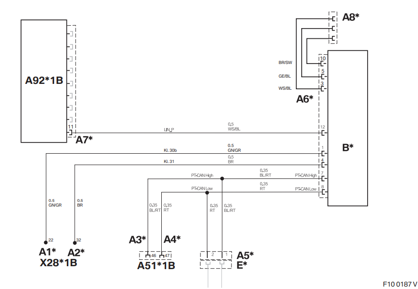
| A1* | With miniature connector G to the cable on left door wiring harness X5*1B, PIN 22 |
| A2* | With miniature connector G to the cable on left door wiring harness X5*1B, PIN 32 |
| A3* | Socket contact to A51*1B, PIN 46 |
| A4* | Socket contact to A51*1B, PIN 47 |
| A5* | SW 2-pin plug casing, to socket casing E* |
| A6* | SW 12-pin socket casing, to control unit B* |
| A7* | Socket contact, to steering column switch cluster (SCSC) A92*1B |
| A8* | 3-pin socket casing for optional LAP trigger measuring sensor All of the designations marked with an asterisk (*) apply only to these installation instructions or this wiring diagram. |
CABLE COLORS
BL Blue – GR Grey – RT Red
BO Bordeaux (Burgundy) – L-GN Light green – SW Black
BR Brown – NT Natural – TR Transparent
GE Yellow – OR Orange – VI Violet
GN Green – RO Pink – WS White